OpenPLC and Modbus Slaves
You can attach industrial Modbus slave devices to expand the number of your I/O points. This is particularly useful for systems that don’t have any I/O points at all (in case of OpenPLC running on Windows for example).
Set Up Your Host
The first thing you need to do is set up your host. In other words, you need to have OpenPLC Runtime installed on your system to proceed. You can use any of the listed devices on the Getting Started page as a host. The most common options are Windows, Linux and Raspberry Pi. Just follow the instructions on the page to have it installed and then move to the next step.
Add A Slave Device to OpenPLC
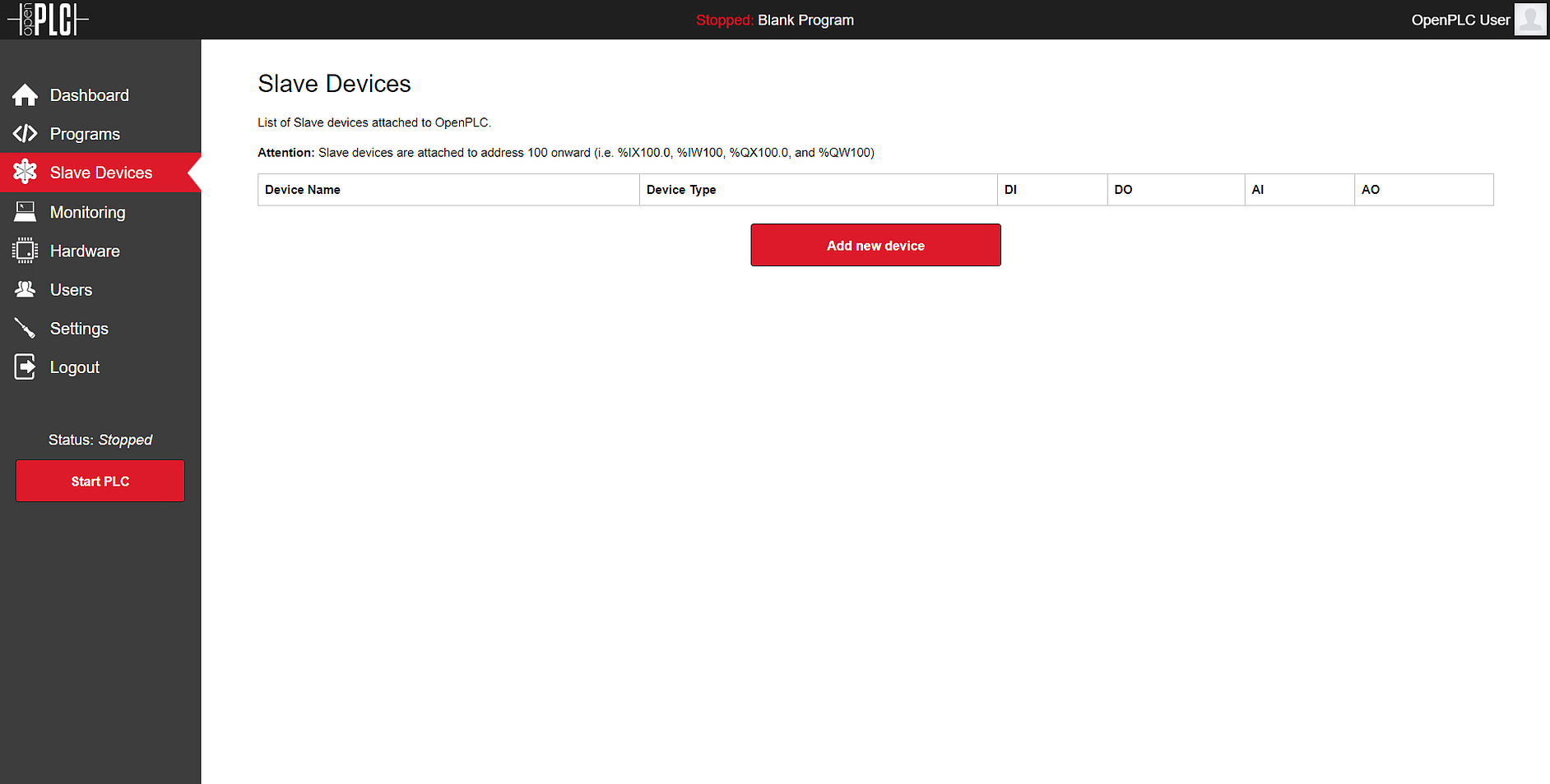
To add a slave device, launch OpenPLC Runtime on your host, log in, go to Slave Devices on the menu and click on “Add new device”.

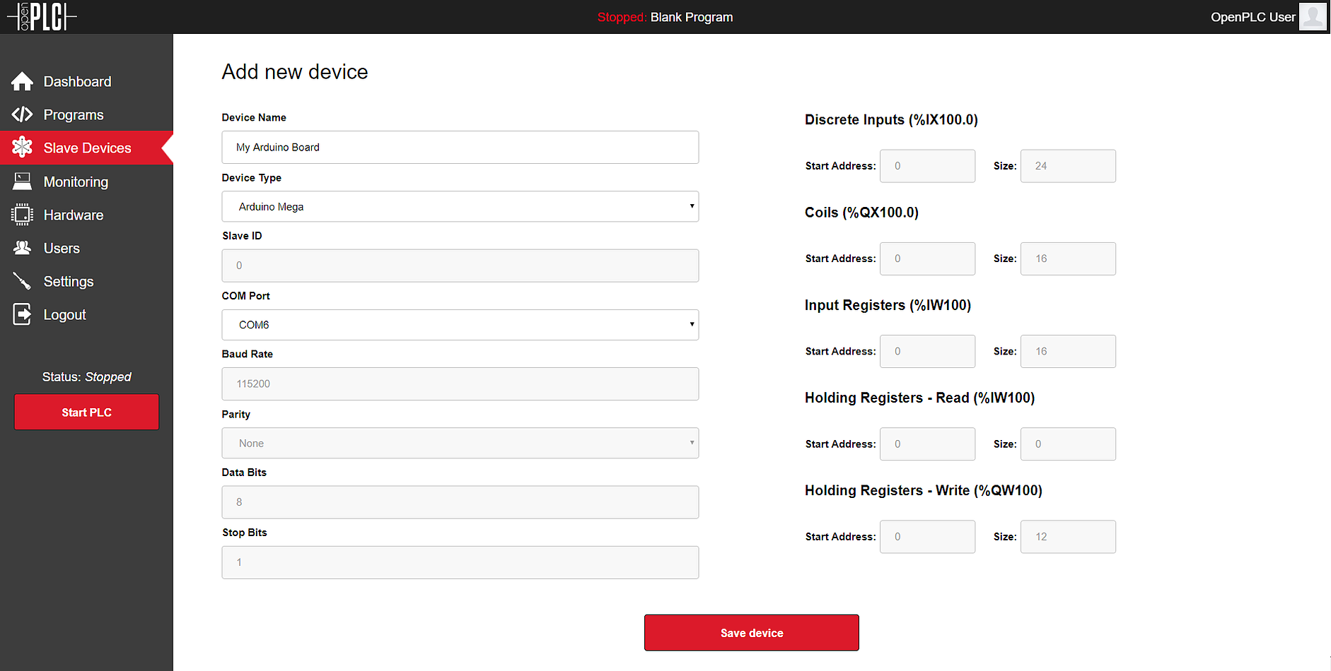
On the new screen that appears, fill out the name for your slave device (it can be anything, but just please avoid non-English characters like ç, é, ó, ñ), and then select “Generic Modbus TCP Device” or “Generic Modbus RTU Device” under Device Type.
TCP devices are the ones with TCP/IP support. RTU devices are only accessible through the serial network (usually RS485). The form will expand or shrink depending on the device type selected. Fill out all the information requested according to your device specifications.
The right side of the page is used to configure the Modbus registers you want
to read and write. You can define the address of the first register and the
range, which means how many registers after the first one you want to be
read/written. These registers will then be mapped to OpenPLC internal
variables, located at %IX100.0, %QX100.0, and so on…

Click on “Save device” and you’re good to go! Just start the PLC and your board will be communicating over WiFi with OpenPLC Runtime.
Pin Mapping
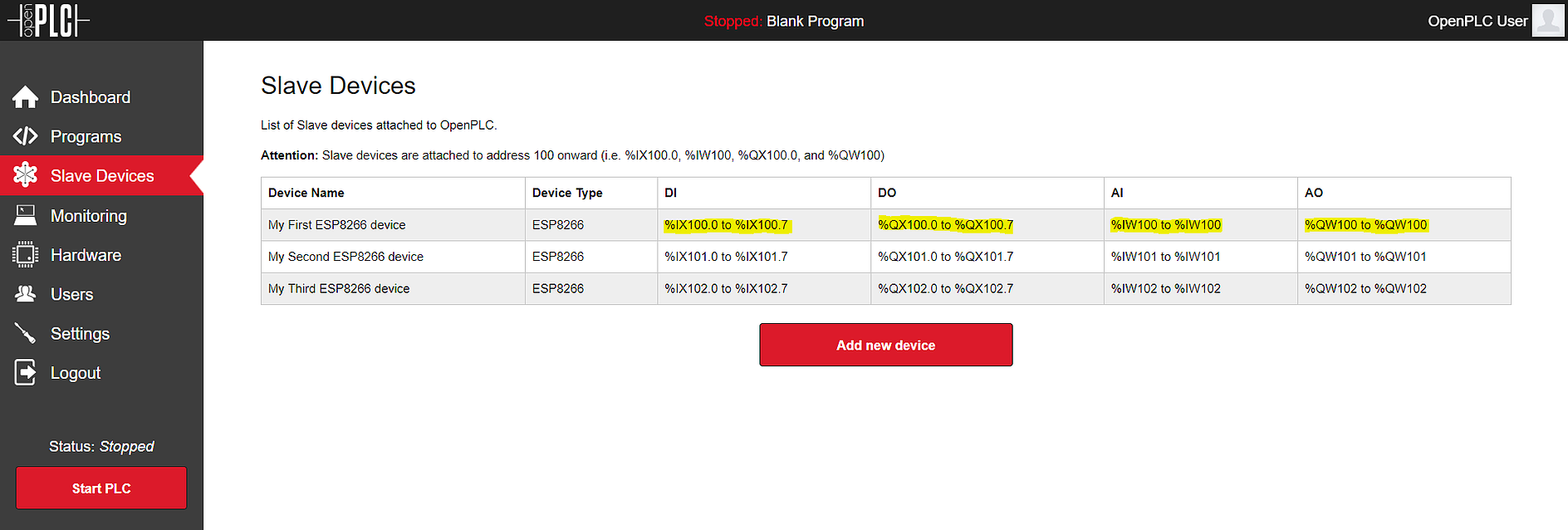
The pin mapping for your Modbus device depends on its position on the slave devices list and the number of registers it has. OpenPLC supports multiple slave devices at the same time, and they all add up together on the address space. Below you can see a list of three ESP8266 devices added up together, and the respective address space reserved for them.

From the table you can see the specific OpenPLC addresses for each device, where it starts and where it ends. For example, each ESP8266 on this list has 8 digital inputs, 8 digital outputs, 1 analog input, and 1 analog output. Therefore, the first device has the 8 digital inputs mapped on %IX100.0 to %IX100.7. All the other inputs and outputs follow the same pattern.